GCPs and GNSS: how to get drone maps to line up
A practical guide to ground control points and GNSS for accurate drone maps, drawn from my UAV photogrammetry work at IIT Roorkee using Emlid Reach RS3 and Trimble DA.

The short answer
If you want a drone map to sit in the right place on Earth, you need two things working together: ground control points (GCPs) that you survey on the ground, and a GNSS receiver accurate enough to measure them. The GNSS gives you trustworthy coordinates. The GCPs carry those coordinates into your photogrammetry software so the whole model snaps onto real-world positions. Skip this step and your map can drift by metres, even when it looks sharp on screen.
I learned this in the field during my research internship at IIT Roorkee, working on UAV photogrammetry with GNSS ground control. This post is the plain version of what I wish someone had told me before my first survey.
Why drone maps drift without ground control
A drone records a GPS position for every photo it takes. That onboard GPS is fine for flying, but it is not survey grade. It can be off by several metres horizontally and even more vertically. When the photogrammetry software stitches hundreds of images into an orthomosaic and a digital surface model, it carries that error straight into the final product.
The map will still look beautiful. Roads will be crisp, rooftops sharp. The problem only shows up when you put it next to other data, a cadastral layer, a Sentinel-2 scene, an older survey, and the features sit in slightly the wrong place. For research and any kind of change detection, that offset quietly ruins your conclusions.
Ground control fixes this. A GCP is simply a clearly marked point on the ground whose exact coordinates you have measured. You place several across your survey area, photograph them from the drone, then tell the software, this pixel is actually at this coordinate. The software uses those anchors to correct the whole block.
What GNSS actually does here
GNSS stands for Global Navigation Satellite System, the umbrella term that covers GPS, GLONASS, Galileo, BeiDou and others. A survey-grade GNSS receiver listens to many of these constellations at once and, with the right correction method, gets you down to centimetre-level positions.
That is the leap that matters. Your phone gives metres. A proper GNSS rover gives centimetres. That precision is what makes a GCP worth placing.
At Roorkee I worked with two receivers that are common in this space:
- Emlid Reach RS3 — a multi-band GNSS receiver with built-in tilt compensation. It is friendly to set up, runs RTK and PPK comfortably, and the tilt feature means you do not always have to perfectly level the pole over a point.
- Trimble DA — part of Trimble's high-precision ecosystem, used where you want a robust, professional-grade survey workflow.
Both give you the same end goal: a coordinate you can trust on a GCP marker.
RTK and PPK: two ways to get centimetres
A single GNSS receiver on its own is not accurate enough. You need a correction. There are two main ways to do it, and the difference is mostly about when the correction happens.
RTK (Real-Time Kinematic)
With RTK, a base station sits over a known point and streams live corrections to your rover as you walk. You see the centimetre-accurate position instantly in the field, and the receiver tells you when it has a fixed solution. This is great for marking GCPs quickly and confirming on the spot that each point is good.
The catch is that RTK needs a live radio or internet link between base and rover. In remote terrain, that link can drop.
PPK (Post-Processed Kinematic)
With PPK, the base and rover both just log raw data. You do the correction later on a computer, matching the two logs after the survey. There is no live link to lose, so it is more forgiving in difficult field conditions, and you can often recover good positions even when RTK would have struggled.
The trade-off is that you do not get instant confirmation in the field, you find out the quality back at the desk.
In practice: many surveys use RTK to mark and check points live, while still logging raw data so PPK is available as a backup. Belt and braces. When you are far from town with one chance to collect data, that redundancy is worth the small extra effort.
A field workflow that works
Here is the sequence I follow, kept simple:
- Plan the GCP layout first. Spread points across the whole area, including the corners and the middle, not bunched in one spot. For elevation accuracy, vertical spread matters as much as horizontal.
- Lay clear targets. Use markers with good contrast against the ground so you can pinpoint the exact centre in the imagery later. The centre is your coordinate, so it has to be unambiguous.
- Set up the base over a known or logged point. Let it settle and start logging.
- Survey each GCP with the rover. Wait for a fixed solution, hold the pole steady, and record. Note the point ID against its marker so you do not mix them up.
- Fly the mission with enough overlap, and make sure every GCP target is clearly visible in several photos.
- Keep some points as checkpoints. Do not feed every surveyed point into the software as control. Hold a few back. After processing, compare the software's position for those checkpoints against your surveyed values. That residual is your honest accuracy estimate.
- Mark GCPs in processing. In your photogrammetry software, click each target in the images and enter its surveyed coordinate. Re-optimise, then read the error report.
That checkpoint step in particular is what separates a map you can defend from one you just hope is right.
Common mistakes I have seen
- Too few GCPs, all clustered together. The corners of your area drift because nothing is anchoring them.
- Forgetting vertical control. Horizontal can look great while heights are off. If elevation matters to your study, plan for it deliberately.
- Mixing up coordinate reference systems. Your GNSS, your GCPs, and your output all have to agree on the same CRS and datum. A mismatch here causes large, confusing shifts.
- Sloppy pole work. A receiver that is not level (or whose tilt compensation is not calibrated) over the marker centre quietly adds error to every point.
Why this matters for research
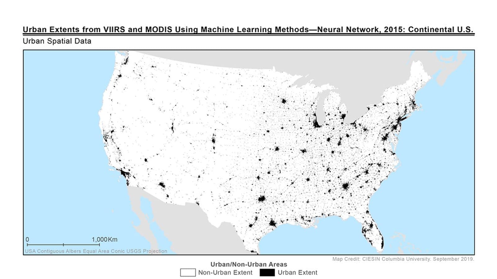
In my work on land and water indices across Punjab and on industrial impact in Delhi NCT, accurate georeferencing is not a nice-to-have. When you are comparing NDVI, NDWI or NDBI over time, or overlaying drone-derived models with satellite data from Sentinel-2 or Landsat, everything has to line up at the pixel level. GCPs and good GNSS practice are what let a drone survey join that wider stack of data honestly.
Get the ground control right, and the rest of the analysis can be trusted. Get it wrong, and every clever thing you do downstream is built on a map that is quietly in the wrong place.
That, in one line, is why we carry the tripod up the hill.